Battery Management System - LTC6804
Author: David M. CaditzOverview
The LTC6804-2 is a battery monitor IC that can monitor up to 12 series connected batteries. It has five general purpose IO pins which can be used to measure sensor values ( e.g., battery temperatures) or control external relays. It also has 12 balancing control outputs for passive battery pack balancing. The LTC6804-2 can be controlled, and data registers can be read, through an 4-wire SPI interface.
The LTC6804-2 can fairly easily interface with an Adruino microcontroller board such as an Arduino Uno. I chose a stacked system with the LTC6804 PCB deisgned as an Arduino shield. The complete system comprises an Arduino Uno, a custom designed LTC6804 BMS board, a balance board and optionally an Xbee wireless mesh network shield to communicate with a monitoring station.
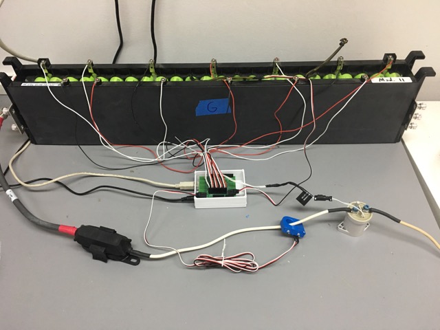
On the test bench
Theory of Operation
The BMS is configured for a battery pack are composed of A123 LiFePO4 cylindrical batteries in 12S8P configuration. The A123 cells have the following characteristics:
| Nominal capacity | 2.3Ah |
| Min discharge voltage: | 2.0 V |
| Max charge voltage: | 3.8V |
| Max continuous charge current: | 10A |
| Max continuous discharge current: | 60A |
| Max recommended temperature | 70C |
The function of the BMS is to maintain the pack within the above specifications. When one or more of the 8P sections of the battery pack are found to be out of range, the BMS deactivates the appropriate relay to isolate the pack. The charge relay disconnects the pack from the charger when an over-voltage or over-current state is detected. The discharge relay disconnects the pack from the load when an under-charge state or load over-current is detected. In addition, both relays are deactivated when an over-temperature state is detected. Care should be taken when a relay is deactivated since the BMS may reactivate the relay when the fault state is eliminated, supplying power to the load. Always assume the battery pack is live and disconnect manually before performing work on the electrical system.
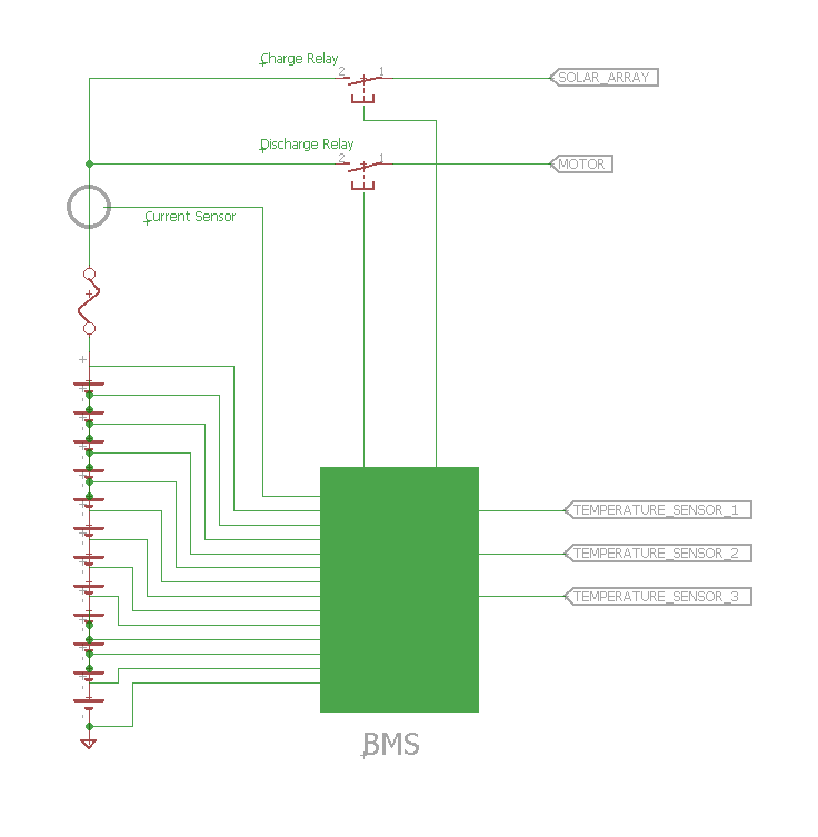
Connection diagram
BMS Circuit
The BMS circuitboard was designed using Eagle CAD. The PCB is designed to plug in to an Arduino Uno, which is programmed to control the LTC6804 through the 4-wire SPI interface at pins 41-44. The arduino reads the data collected by the LTC6804 such as cell voltages, current and cell temperatures and also controls peripheral circuitry such as relays. The schematic is provided in Figure 1. R-C filters are provided for each cell monitoring input. Analog inputs A2 - A5 are connected to the corresponding Arduino analog input pins, with +5 and ground also routed to each connector. A0 connects to a LEM hall effect sensor which outputs approximately Vin/2 at zero current where Vin is nominally 12 volts. A separate voltage divider connects to A1 which monitors the true Vin, which may vary with the state of charge of the external 12V supply. The relay drivers are controlled by the Arduino's digital pins 8 and 9.
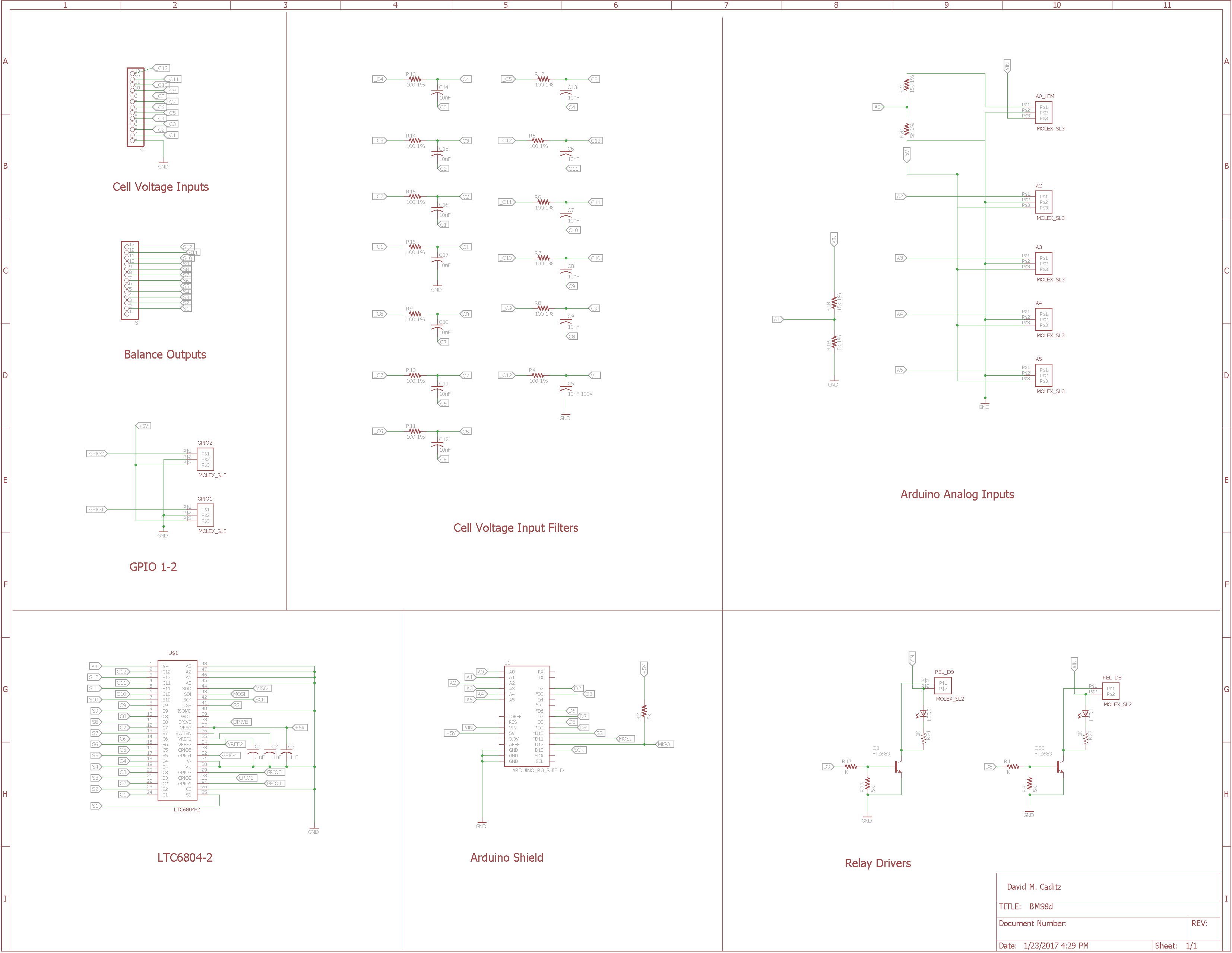
BMS Schematic
PCB Layout and Routing
The PCB is a 2-layer design using surface mount components. Most discreet components use 0805 packages since smaller packages are difficult to solder by hand. The LTC6804 itself is provided as a 48 pin SSOP with 0.5mm lead spacing which can be challenging to solder. The bottom layer is specified as a ground plane to minimize noise. Eagle CAD did a fairly good job of trace routing after the components were placed in reasonable locations with enough space between.
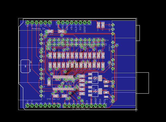
BMS PCB Layout
PCB Assembly
Prototype BMS PCBs were soldered by hand using a Weller WESD51 temperature controlled soldering station with an ETB ET series 0.093 "screwdriver" tip and 0.3mm solder. Although smaller tips may seem better for intricate work, they do not retain heat and make the job more difficult. It works well to place a bit of solder on one pad, place the device and tack down that pad. The remaining pads can then be soldered without the part moving. A different technique is needed for the LTC6804 SSOP package which has quite narrow pin spacing. One method uses large amount of solder which is allowed to bridge the pins. The excess is then removed with high quality solder wick. For the second method, pre-apply a small amount of solder on each pad. The IC is then placed and tacked down pin by pin. It is good practice to place the most difficult component first so that if it fails, the remaining components are not wasted. Work can be done under a magnifying glass. Taking a photo with your phone and zooming in is a good way to inspect for cold joints or bridging. A hot air rework station is also useful to remove surface mount components when all else fails.
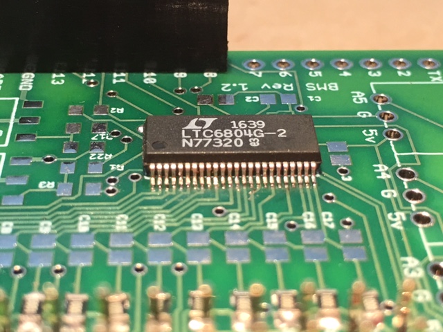
Soldering surface mount components
Connections
The BMS board is designed to be connected to an Arduino UNO as a standard shield. It draws power directly from the Arduino, which should be plugged in to a 12V supply. The BMS board has input connectors for two temperature sensors and a LEM Hall effect current sensor. The board uses TE/APM 5-103634-2 three position right angle header connectors for these sensor inputs. The sensor cables should mate to these headers with the pin definitions (gnd, +5v and signal) indicated on the circuitboard. There are optional slots on the circuitboard for two additional temperature sensor inputs and two general purpose input/outputs (GPIO). Temperature sensors are MPC9700 3-pin Thermistor ICs or similar: Datasheet The arduino code is calibrated for a 50 amp LEM HTB 50-P/SP5 current sensor. Other current sensors can be used, but the code may need modification if the sensor has a different nominal current rating. There are two relay control outputs which use TE/APM 103635-1 two position headers. One relay header is for the charge relay and the other is for the discharge relay. These can be repurposed for other uses in the arduino code. The board supplies power to the relay coils with a maximum rated current of 9 amps, but this may be limited by your arduino power supply. Note: powering the Arduino from USB cable will probably not provide enough current to keep the relay coils energized. Battery sense wires plug into the top row of the 13 pin, 0.1 pin spacing header. Respect the indicated polarity when connecting the battery sense wires. Reversing the polarity may cause permanent damage to the BMS board.
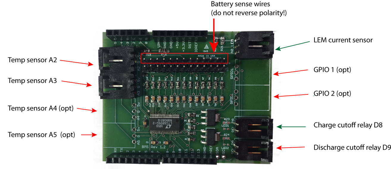
BMS Headers
Arduino Code
The Arduino code for the BMS is available by clicking the image to the right. Several required libraries for interacting with the LTC6804 are specified in the header. These can be found on the Linear Technology website here. Download and extract LTSketchbook.zip to find the listed libraries. The code poles the LTC6804 every 5 seconds and reads the battery cell voltages, pack temperature sensors and total current. If any values are out of the pre-defined safe range, the arduino opens a relay to disconnect the battery pack. The code writes cell voltages both to the Serial monitor and to an Xbee wireless mesh network. The battery pack can be monitored remotely using the Xbee interface.
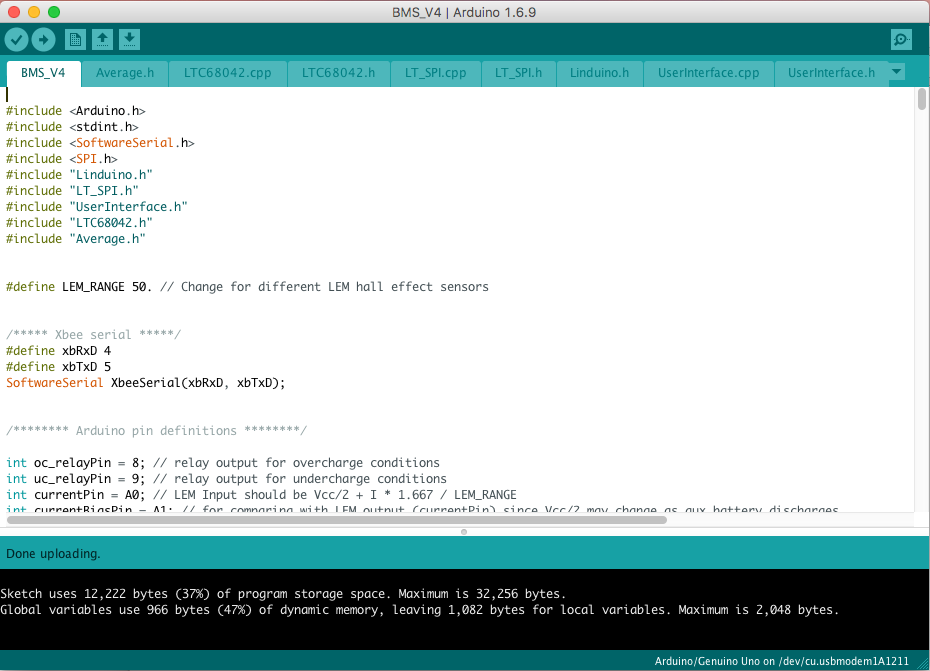
Arduino BMS Code